
SQL Server Fundamentals: How Relational Storage, Data Pages, and Clustered Indexes Actually Work
Learn how SQL Server organizes relational storage. Master 8KB data pages, extents, heaps vs clustered indexes, and B-Tree seeks to eliminate slow queries.

Author & Creator · CodeToClarity
Most software engineers interact with relational databases through Object-Relational Mappers (ORMs) such as Entity Framework Core, Dapper, or Hibernate. Developers write LINQ queries, map entities to tables, apply database migrations, and assume the database engine handles physical data access efficiently. In development environments with a few thousand rows, queries execute in single-digit milliseconds regardless of schema design. When application tables scale past 100,000 or 1,000,000 rows in production, query performance suddenly collapses. API endpoints experience high latency, database CPU usage spikes to 100 percent, and mysterious deadlocks degrade user workflows.
Resolving these production bottlenecks requires looking past logical query syntax and understanding the physical storage engine underneath. SQL Server does not see tables as abstract spreadsheets or JSON documents. Instead, it reads, writes, caches, and organizes data using rigid physical units: 8KB data pages, 64KB extents, allocation bitmaps, and balanced B-Tree hierarchies. This comprehensive architectural guide examines how SQL Server organizes data on disk, dissects the anatomy of an 8KB page, explains the structural differences between Heaps and Clustered Tables, and demonstrates how index architecture dictates memory consumption and disk I/O.
Key Takeaways
- The 8KB Data Page (8,192 bytes) is the atomic unit of disk and memory transfer in SQL Server: the database engine never reads or writes single rows or individual columns from disk.
- A table without a clustered index is a Heap, storing unordered records tracked by Index Allocation Map (IAM) pages and referenced by 8-byte Row Identifiers (RIDs).
- Expanding variable-length columns in Heap tables triggers Forwarded Records, leaving behind a 16-byte forwarding stub and turning single-page lookups into multiple random page reads.
- A Clustered Index is not an auxiliary lookup pointer table: the leaf level of a Clustered Index B-Tree physically is the table data sorted by the clustered key.
- A Primary Key is a logical integrity constraint that enforces uniqueness, whereas a Clustered Index is a physical storage arrangement; they do not have to be created on the same column.
- Choosing a clustered key requires adhering to the NUMS criteria (Narrow, Unique, Monotonic, Static); using random GUIDs (
NEWID()) causes severe 50/50 page splits, index fragmentation, and buffer pool memory waste.
1. The Physical Foundation: 8KB Data Pages, Extents, and the Buffer Pool
In SQL Server, the fundamental unit of disk input/output (I/O) and memory caching is the 8KB Data Page (8,192 bytes). The database engine never reads a single column or single row directly from disk storage; it always reads an entire 8KB page into the RAM Buffer Pool.
When a query requests a single row from an order table, SQL Server determines which 8KB page holds that row, loads all 8,192 bytes into memory if not already cached, and processes the record inside the buffer cache. Understanding this page-based access model is essential for writing efficient queries and diagnosing physical performance bottlenecks. As detailed in the Microsoft Learn Pages and Extents Architecture Guide, data files (.mdf and .ndf) in SQL Server are physically partitioned into contiguous 8KB pages numbered sequentially from 0 to N.
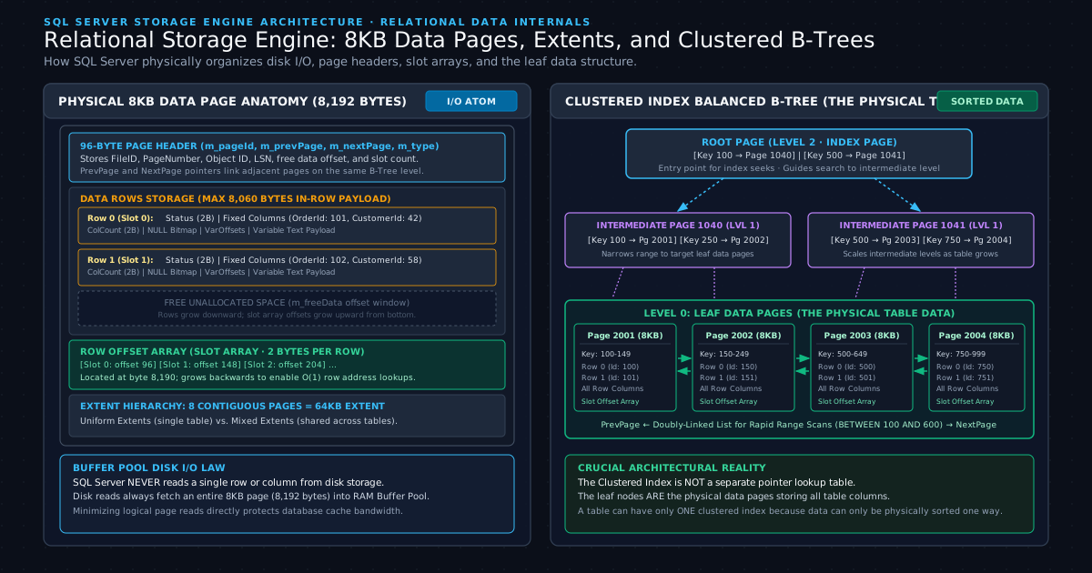
Anatomy of an 8KB Data Page
Every 8KB data page has a strict physical structure consisting of three distinct sections:
- The 96-Byte Page Header: Located at the very start of the page (bytes 0 to 95). The header stores critical page metadata, including:
m_pageId: The physical file number and page number (for example,1:1042).m_type: The page type identifier (Type 1 for Data Pages, Type 2 for Index Pages, Type 10 for IAM pages).m_prevPageandm_nextPage: 6-byte pointers storing the previous and next page addresses at the same B-Tree level, forming a double-linked list.m_objId: The object ID of the table or index that owns the page.m_freeData: The byte offset pointing to the start of free unallocated space.m_slotCnt: The total count of row offset slots registered in the page.m_lsn: The Log Sequence Number of the last transaction log record that modified this page, used by recovery and checkpoint engines.
- The Data Rows Section: Located immediately after the 96-byte header, beginning at byte offset 96. Data rows grow downwards toward the end of the page. Because the header takes 96 bytes and the page footer requires at least 36 bytes for slot pointers, the maximum size of a single in-row data record in SQL Server is 8,060 bytes. If a table schema defines fixed-length columns exceeding 8,060 bytes, SQL Server rejects table creation with an error.
- The Row Offset Array (Slot Array): Located at the very end of the page (byte 8,190) and grows backwards toward the center of the page. Each slot entry consumes exactly 2 bytes and stores an integer offset pointing to the exact starting byte of a data row within that page. When SQL Server looks up a row inside an 8KB page, it does not scan the data bytes sequentially. It performs an O(1) array lookup into the slot array at the end of the page to find the starting memory address of the row.
Anatomy of a Data Row
Individual rows within the page also follow a standardized binary format:
- Status Bits A and B (2 bytes): Store row property flags, such as record type (primary record, forwarded record, or forwarding stub) and whether a NULL bitmap is present.
- Fixed-Length Data Offset (2 bytes): Stores the byte offset where fixed-length columns end.
- Fixed-Length Column Payload: Stores all fixed-width columns (
INT,BIGINT,DATETIME2,CHAR,MONEY). - Column Count (2 bytes): Stores the total number of columns in the row.
- NULL Bitmap: Uses 1 bit per column (ceiling of
NumberOfColumns / 8bytes) to indicate whether each column value isNULL. If a column isNULL, SQL Server does not waste storage bytes for fixed columns. - Variable-Length Column Count (2 bytes): Stores the number of variable-length columns (
VARCHAR,NVARCHAR,VARBINARY) present in the row. - Variable-Length Column Offset Array: Stores 2 bytes per variable-length column, indicating the end offset of each variable value.
- Variable-Length Column Payload: Stores the actual text or binary content.
Extents: Uniform vs. Mixed
To manage space allocation efficiently, SQL Server does not allocate individual 8KB pages to tables one by one. Instead, it groups 8 contiguous pages into a 64KB structure called an Extent.
SQL Server utilizes two types of extents:
- Mixed Extents: Extents shared by up to 8 different database objects. In older SQL Server versions (SQL Server 2014 and earlier), newly created tables were allocated individual pages inside mixed extents until the table reached 8 pages, after which it received uniform extents.
- Uniform Extents: Extents owned entirely by a single database object. All 8 pages (64KB) are dedicated exclusively to that table or index. Starting with SQL Server 2016, database engine default configuration allocates uniform extents from the very first row via
AUTOGROW_ALL_FILES.
Space allocation within data files is tracked through specialized allocation map pages:
- Global Allocation Map (GAM): Tracks which extents are currently allocated. Each bit represents an extent (1 bit = 64KB). A single GAM page tracks 64,000 extents (nearly 4GB of data file space). A bit value of
1indicates the extent is free;0indicates it is allocated. - Shared Global Allocation Map (SGAM): Tracks which extents are mixed extents that currently have at least one unused page available.
The Buffer Pool Law
The architectural relationship between disk storage and memory is governed by the Buffer Pool:
Retrieving an 8KB page from physical NVMe disk storage is roughly 1,000 times slower than reading it from RAM cache. When SQL Server executes a query, it must first check the Buffer Pool in memory. If the page is present, it registers a Logical Read (cache hit). If the page is not in memory, the engine must issue physical disk commands to load the page into the Buffer Pool, registering a Physical Read.
Because disk I/O occurs in 8KB increments, scanning 10,000 pages requires reading 80 megabytes of data into RAM. If a query selects columns from a poorly indexed table, SQL Server fills the Buffer Pool with unnecessary pages, forcing active cache data out of memory and degrading overall database throughput. Understanding query processing order also prevents wasteful buffer retrieval; developers can review Why SELECT Executes Last in SQL to understand how the relational engine processes filters before data projection.
2. Heap Tables vs. Clustered Tables: How SQL Server Organizes Rows
In SQL Server, every relational table exists in one of two physical storage formats: it is either a Heap table with no defined physical order, or a Clustered Table organized into a balanced B-Tree sorted by a clustered key.
Understanding the internal difference between these two structures explains why unindexed tables degrade under high transaction volume and why specific data modification operations cause unexpected disk I/O amplification.
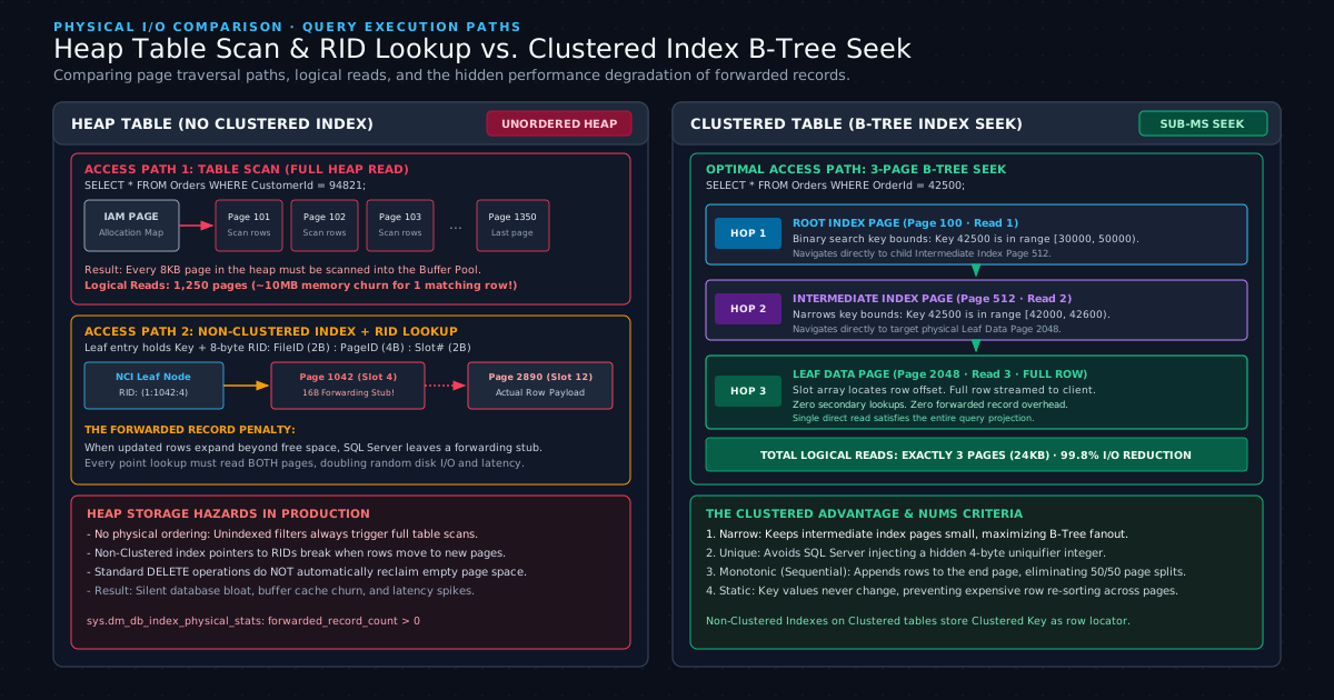
What is a Heap Table?
A Heap is a table that has no clustered index. The data rows are stored on 8KB data pages without any particular order, and the pages themselves are not linked together in a sequence.
The characteristics of a Heap include:
- No Physical Ordering: Rows are inserted wherever free space is available in an allocated page. If page 4 has 200 bytes free and a newly inserted row requires 150 bytes, SQL Server places the row on page 4 regardless of primary key values.
- Tracked by IAM Pages: Because heap pages do not have
m_prevPageorm_nextPagepointers linking them together, SQL Server relies entirely on Index Allocation Map (IAM) pages to track which pages belong to the heap. An IAM page contains a bitmap of extents allocated to the object. - The Row Identifier (RID): When secondary non-clustered indexes are built on a heap, they locate rows using an 8-byte binary Row Identifier (RID). The RID format consists of:
FileID(2 bytes): Identifies the database data file.PageID(4 bytes): Identifies the specific 8KB page within the file.SlotNumber(2 bytes): Identifies the exact slot in the page offset array.
When a query runs against a heap without an applicable index (for example, SELECT * FROM Orders WHERE CustomerId = 94821;), SQL Server has no way to navigate directly to matching rows. The query engine must read the table IAM page and perform a Table Scan, reading every single 8KB page allocated to the heap into the Buffer Pool from first page to last page.
The Hidden Killer: Forwarded Records
The single most destructive performance hazard inherent to Heap tables in high-concurrency production systems is the Forwarded Record.
Consider an e-commerce orders table stored as a Heap:
- An order record is inserted with
Notes VARCHAR(500) = NULL. Because the column is null, the row consumes only 40 bytes on Page 1042. - Over time, other rows are inserted onto Page 1042 until the page reaches full capacity (8,060 bytes used, 0 bytes free).
- The customer updates their order, adding customer service notes:
SET Notes = 'Customer requested expedited delivery with special gate code 9921'. The row payload expands from 40 bytes to 140 bytes. - SQL Server attempts to write the additional 100 bytes back to Page 1042, but Page 1042 has zero free space remaining.
In a Clustered Index, SQL Server would perform a page split to make room while keeping data ordered. In a Heap, SQL Server does something different:
- It removes the data row payload from Page 1042.
- It writes the expanded row payload onto a completely different page (for example, Page 2890) where free space exists.
- On the original page (Page 1042), in the original slot, SQL Server leaves behind a 16-byte Forwarding Stub. The forwarding stub contains a pointer storing the new location:
Page 2890, Slot 12. - The row status bits are updated to mark it as a
FORWARDING_STUB, and the target record on Page 2890 is marked as aFORWARDED_RECORD.
Non-Clustered Index -> Points to RID (1:1042:Slot 4)
                           │
                           ▼
                    [Page 1042, Slot 4]
                 (16-Byte Forwarding Stub)
                           │
                           ▼ Pointer: (1:2890:Slot 12)
                    [Page 2890, Slot 12]
                    (Actual Data Payload)
Why does SQL Server use forwarding stubs? If SQL Server simply moved the row to Page 2890 and updated the RID, it would be forced to locate and update every single non-clustered index on that table to point to the new RID. On tables with multiple secondary indexes, updating every index on an ordinary UPDATE statement would cause severe write latency and deadlock risk.
However, the forwarding stub creates a permanent reading penalty:
- Any non-clustered index lookup searching for that order row visits Page 1042 first.
- The storage engine encounters the forwarding stub and issues a second, separate I/O operation to read Page 2890.
- A query that should have required 1 page read now requires 2 page reads. In tables with high update activity, thousands of forwarded records accumulate, doubling or tripling physical disk I/O and fragmenting heap space.
- In addition, standard
DELETEoperations on heaps do not deallocate empty pages back to the database file; empty pages remain allocated to the heap until the table is rebuilt.
What is a Clustered Table?
A Clustered Table is a table that has a Clustered Index. In a clustered table, the physical data rows are not stored randomly; they are organized into a balanced B-Tree structure sorted by the clustered index key.
The definitive architectural reality of a Clustered Index is:
The leaf level of a Clustered Index IS the physical table data.
Unlike non-clustered indexes, which maintain a separate copy of index keys pointing back to the table, a clustered index does not point to data. The leaf pages of the clustered index B-Tree contain all columns for every row.
A Clustered Index B-Tree consists of three logical tiers:
- The Root Level (Single Page): The top-level 8KB index page that serves as the entry point for all index seeks. It contains navigation pointers matching key ranges to child intermediate pages.
- Intermediate Levels (Index Pages): Zero, one, or more intermediate levels of 8KB index pages. Each record in an intermediate page consists of two values: a clustered key value and a 6-byte pointer storing the physical address (
FileID:PageID) of the child page at the next level down. - The Leaf Level (Data Pages): The bottom level of the B-Tree. These are standard 8KB data pages storing all table columns. The leaf pages are doubly linked via
m_prevPageandm_nextPagepointers in their 96-byte headers, allowing fast bidirectional sequential scans for range queries (BETWEEN,>,<).
Because the leaf level is the data, a table can have only one clustered index. Data rows can only be physically sorted on disk in one order at any given time.
3. The Great Misconception: Primary Key vs. Clustered Index
A Primary Key is a logical integrity constraint defined by relational database theory to guarantee uniqueness and entity integrity, whereas a Clustered Index is a physical storage structure that dictates how records are physically arranged on disk.
Confusing these two concepts is one of the most widespread architectural mistakes made by application developers and database administrators alike.
Logical Constraints vs. Physical Organization
To clarify the distinction between logical rules and physical storage:
| Architectural Property | Primary Key | Clustered Index |
|---|---|---|
| Architectural Layer | Logical Data Modeling (Relational Constraint) | Physical Storage Engine (Data Structure) |
| Core Purpose | Guarantees entity uniqueness; rejects NULL values | Dictates physical on-disk sort order of table rows |
| Database Limit | Exactly 1 per table | Maximum 1 per table (or 0 if Heap) |
| Foreign Key Target | Can be referenced by foreign key constraints | Cannot be directly referenced by foreign keys (unless backed by a unique constraint) |
| Leaf Level Contents | N/A (Logical constraint enforced by an index) | Stores the entire row data for all table columns |
| Default in SSMS | Automatically created as CLUSTERED | Created automatically when PRIMARY KEY is declared without keywords |
When a developer executes standard Data Definition Language (DDL) syntax in SQL Server:
CREATE TABLE CodeToClarityOrders (
    OrderId INT IDENTITY(1,1),
    CustomerGuid UNIQUEIDENTIFIER NOT NULL,
    OrderDate DATETIME2 NOT NULL,
    TotalAmount DECIMAL(18,2) NOT NULL,
    CONSTRAINT PK_CodeToClarityOrders PRIMARY KEY (CustomerGuid)
);
Because the developer omitted the index type, SQL Server automatically applies its default behavior: CONSTRAINT PK_CodeToClarityOrders PRIMARY KEY CLUSTERED (CustomerGuid).
The database engine creates a primary key constraint and physically organizes the entire table on disk sorted by CustomerGuid. If CustomerGuid is populated with random GUIDs (NEWID()), the developer has inadvertently created a fragmented, low-performance table structure simply because they accepted SQL Server's default syntax.
Decoupling the Primary Key from the Clustered Index
SQL Server does not require the Primary Key to be the Clustered Index. A table can possess a Non-Clustered Primary Key to enforce entity uniqueness, while maintaining a Clustered Index on an entirely different column to optimize high-volume queries:
CREATE TABLE CodeToClarityCustomerEvents (
    EventId UNIQUEIDENTIFIER NOT NULL DEFAULT NEWID(),
    TenantId INT NOT NULL,
    CreatedDateUtc DATETIME2 NOT NULL,
    Payload NVARCHAR(MAX) NULL,

    /* Logical Constraint: Guarantees EventId is unique across the system */
    CONSTRAINT PK_CodeToClarityCustomerEvents
        PRIMARY KEY NONCLUSTERED (EventId),

    /* Physical Organization: Physically sorts table by Tenant and Date on disk */
    INDEX CIX_CodeToClarityCustomerEvents_TenantDate
        CLUSTERED (TenantId, CreatedDateUtc)
);
In this decoupled architecture:
- The application can query individual events by
EventIdwith unique validation. - High-throughput production reporting queries that filter by
TenantIdand order byCreatedDateUtcread contiguous physical 8KB pages sequentially without performing expensive index lookups or memory sorts.
For developers designing transactional architectures, understanding how schema constraints influence physical writes is critical; see Why Database Performance Fails: Schema Design Pitfalls for related normalization and storage patterns.
4. The NUMS Criteria: Choosing the Right Clustered Key
Choosing an optimal clustered index key requires evaluating how data is written, updated, and queried over time. Senior database engineers evaluate clustered key candidates using the NUMS criteria:
Evaluating each dimension illustrates why key selection directly governs storage engine health:
1. Narrow (Small Data Type)
The clustered key should consume as few bytes as possible. An INT (4 bytes) or BIGINT (8 bytes) is vastly superior to a UNIQUEIDENTIFIER (16 bytes) or a composite key spanning multiple string columns (50+ bytes).
Why does key width matter? As demonstrated in Section 5 below, every single non-clustered index created on a clustered table copies the clustered key into every one of its leaf nodes to act as the row locator. If a table has 5 non-clustered indexes and a clustered key consuming 64 bytes instead of 8 bytes, the database wastes tens of gigabytes of disk and Buffer Pool RAM across secondary index trees.
2. Unique
The clustered key must be unique. If a clustered index is created on a non-unique column (such as LastName or Status), SQL Server cannot distinguish between duplicate rows at the B-Tree leaf level.
To resolve this limitation, SQL Server silently injects a hidden 4-byte Uniquifier integer into every duplicate record. If an inserted row contains a key value that already exists, the engine sets the uniquifier to 1, then 2, then 3. This hidden 4-byte overhead widens both the clustered index leaf rows and every secondary non-clustered index row referencing that record.
3. Monotonic (Continuously Increasing)
The clustered key values should increment sequentially as new rows are inserted (IDENTITY, BIGINT sequences, or sequential timestamps).
When keys are monotonic, new rows are always appended to the very last 8KB data page at the end of the B-Tree. When that page reaches 8,060 bytes, SQL Server cleanly allocates a new 8KB page, links it to the previous page, and continues inserting. This eliminates Page Splits and maintains near-zero index fragmentation.
4. Static (Never Modified)
The column values in the clustered key should never be updated.
When a query updates a clustered key column, SQL Server cannot simply overwrite the value in place. Because the clustered key dictates physical order, the storage engine must execute a physical DELETE of the row from its current 8KB page, traverse the B-Tree to find the page corresponding to the new key value, and execute an INSERT. This generates double the transaction log traffic and increases lock escalation risks.
The Random GUID Disaster: Anatomy of a 50/50 Page Split
To understand the consequence of violating the Monotonic rule, examine what occurs when an application uses random GUIDs (NEWID()) as the clustered index key.
/* DANGEROUS PATTERN IN HIGH-WRITE ENVIRONMENTS */
CREATE TABLE CodeToClarityTransactions (
    TransactionId UNIQUEIDENTIFIER NOT NULL DEFAULT NEWID(),
    Amount DECIMAL(18,2) NOT NULL,
    CreatedAt DATETIME2 NOT NULL,
    CONSTRAINT PK_Transactions PRIMARY KEY CLUSTERED (TransactionId)
);
Random GUIDs are distributed uniformly across hexadecimal space. When the application inserts 10,000 transactions:
- Row 1 has key
8a12...and is written to Page 100. - Row 2 has key
1f04...and must be written to Page 40 (earlier in the B-Tree). - Row 3 has key
d9c1...and must be written to Page 180. - Soon, every page in the table is 95 to 100 percent full.
- A new row arrives with key
8a15.... By definition of sorted order, this row belongs physically on Page 100 between key8a12...and8a18.... - But Page 100 is completely full (8,060 bytes used). There is zero space to insert the new record.
SQL Server is forced to perform a 50/50 Page Split:
- It allocates a brand new 8KB page (Page 250) from disk.
- It moves approximately 50 percent of the rows from Page 100 onto Page 250.
- It writes the new row
8a15...onto the appropriate page. - It updates the double-linked list pointers (
m_prevPageandm_nextPage) on Page 100, Page 250, and their adjacent neighbors. - It inserts a new navigation record into the parent intermediate index page. If the intermediate index page is also full, the page split cascades upward toward the root page!
BEFORE SPLIT:
[Page 100: 100% Full (Keys 8a00 to 8a99)]  <- Insert Key 8a15 (NO ROOM!)

AFTER 50/50 SPLIT:
[Page 100: 50% Full (Keys 8a00 to 8a49)] <-> [Page 250: 50% Full (Keys 8a50 to 8a99)]
The operational consequences of 50/50 page splits in production include:
- Massive Write Amplification: An insert of 100 bytes suddenly generates 4KB of memory movement and heavy transaction log generation.
- Index Fragmentation: Physical page ordering no longer matches logical B-Tree ordering. Pages become scattered randomly across data files.
- 50% Memory Waste in Buffer Pool: Because pages are left half-empty after splits, caching the table requires twice as many 8KB pages in the Buffer Pool, cutting effective database RAM capacity in half.
When client applications require GUID identifiers for distributed generation, developers should use sequential alternatives such as SQL Server's NEWSEQUENTIALID() or modern UUIDv7 generators, or separate the GUID primary key from a sequential integer clustered index.
5. Non-Clustered Indexes: Row Locators on Heaps vs. Clustered Tables
A Non-Clustered Index is a separate B-Tree structure whose leaf nodes contain only the indexed key columns and a Row Locator pointing back to the full data row.
The physical implementation of that row locator depends entirely on whether the underlying table is a Heap or a Clustered Table.
NON-CLUSTERED INDEX LEAF RECORD:
┌──────────────────────────────┬─────────────────────────────────────────────────┐
│     Index Key Columns        │                   Row Locator                   │
├──────────────────────────────┼─────────────────────────────────────────────────┤
│ CustomerId (4B), Status (2B) │ RID (8B): File:Page:Slot   [If Table is a HEAP] │
│                              │ Clustered Key: OrderId (8B) [If CLUSTERED TABLE]│
└──────────────────────────────┴─────────────────────────────────────────────────┘
Row Locator on a Heap: The 8-Byte RID
On a Heap table, the row locator is a physical 8-byte RID (FileID:PageID:SlotNumber).
- Lookup Process (RID Lookup): When a query executes an index seek on a non-clustered index to retrieve columns not covered by the index, SQL Server navigates the non-clustered B-Tree to find the matching leaf node, reads the 8-byte RID, and performs a direct, single-page read against the exact heap page and slot.
- Vulnerability: As established in Section 2, if the row in the heap expands and becomes a forwarded record, the RID lookup must visit the forwarding stub and follow the pointer to a second page, incurring multiple random disk reads.
Row Locator on a Clustered Table: The Clustered Key
On a Clustered Table, the row locator is not a physical file address; it is the Clustered Index Key of the corresponding row.
- Lookup Process (Key Lookup): When a non-clustered index seeks a matching entry on a clustered table, its leaf node provides the clustered key value (for example,
OrderId = 42500). If the query requests columns not included in the non-clustered index, SQL Server executes a secondary B-Tree traversal called a Key Lookup (Clustered). The engine traverses the clustered index B-Tree from root to leaf to retrieve the full row. - Advantage: Clustered tables never suffer from forwarded records. If a page splits or data is reorganized, the non-clustered indexes do not need to be updated because the logical clustered key value remains unchanged.
The "Wide Clustered Key" Storage Tax
Because every non-clustered index leaf node embeds the clustered key, selecting a wide clustered key levies a massive storage tax across the entire table.
Consider a table with 10,000,000 rows and 4 non-clustered indexes:
By selecting an unnecessarily wide clustered key, secondary indexes consume 1.6 gigabytes of additional memory and disk space solely to store row locators. This extra data reduces the number of index keys that fit onto each 8KB index page, increasing B-Tree depth and requiring additional logical page reads for every query execution.
To optimize secondary indexes, developers can implement covering indexes using the INCLUDE clause; see SQL Query Optimization: Tips to Speed Up Your Database for indexing strategies that eliminate key lookups entirely.
6. Hands-On Verification: Inspecting Data Pages and Measuring Logical Reads in T-SQL
Observing physical storage mechanics directly confirms the architectural principles described above. Developers can spin up a local SQL Server 2022 instance in a Docker container and execute T-SQL commands to inspect page allocations and capture logical reads.
1. Launching SQL Server 2022 via Docker
Run the official SQL Server 2022 container locally:
docker run -e "ACCEPT_EULA=Y" -e "MSSQL_SA_PASSWORD=CodeToClarity#2026" \
   -p 1433:1433 --name codetoclarity-sql -d \
   mcr.microsoft.com/mssql/server:2022-latest
Connect using SQL Server Management Studio (SSMS), Azure Data Studio, or the sqlcmd command-line utility.
2. Creating Benchmark Schemas: Heap vs. Clustered Table
Execute the following script to create a testing database and populate two tables (one Heap, one Clustered Table) with 50,000 identical rows:
CREATE DATABASE StorageInternalsLab;
GO

USE StorageInternalsLab;
GO

/* 1. Create Heap Table (No clustered index) */
CREATE TABLE dbo.OrdersHeap (
    OrderId INT NOT NULL,
    CustomerId INT NOT NULL,
    OrderDate DATETIME2 NOT NULL,
    OrderAmount DECIMAL(18,2) NOT NULL,
    Notes VARCHAR(200) NULL
);

/* 2. Create Clustered Table (Clustered on OrderId) */
CREATE TABLE dbo.OrdersClustered (
    OrderId INT NOT NULL,
    CustomerId INT NOT NULL,
    OrderDate DATETIME2 NOT NULL,
    OrderAmount DECIMAL(18,2) NOT NULL,
    Notes VARCHAR(200) NULL,
    CONSTRAINT PK_OrdersClustered PRIMARY KEY CLUSTERED (OrderId)
);

/* 3. Populate both tables with 50,000 identical rows */
SET NOCOUNT ON;

WITH NumbersCTE AS (
    SELECT 1 AS Num
    UNION ALL
    SELECT Num + 1 FROM NumbersCTE WHERE Num < 50000
)
INSERT INTO dbo.OrdersHeap (OrderId, CustomerId, OrderDate, OrderAmount, Notes)
SELECT
    Num,
    (Num % 500) + 1,
    DATEADD(MINUTE, -Num, SYSUTCDATETIME()),
    CAST((Num % 1000) + 10.50 AS DECIMAL(18,2)),
    'Standard priority order processed via CodeToClarity automated pipeline.'
FROM NumbersCTE
OPTION (MAXRECURSION 50000);

INSERT INTO dbo.OrdersClustered (OrderId, CustomerId, OrderDate, OrderAmount, Notes)
SELECT OrderId, CustomerId, OrderDate, OrderAmount, Notes
FROM dbo.OrdersHeap;
GO
3. Inspecting Physical Page Allocations via Dynamic Management Views
SQL Server provides the Dynamic Management Function sys.dm_db_database_page_allocations to inspect every physical 8KB page allocated to an object:
/* Inspect pages allocated to the Clustered Table */
SELECT
    allocated_page_file_id AS FileId,
    allocated_page_page_id AS PageId,
    page_type_desc AS PageType,
    page_level AS BTreeLevel,
    next_page_page_id AS NextPageId,
    previous_page_page_id AS PrevPageId
FROM sys.dm_db_database_page_allocations(
    DB_ID('StorageInternalsLab'),
    OBJECT_ID('dbo.OrdersClustered'),
    NULL, NULL, 'DETAILED'
)
WHERE is_allocated = 1
ORDER BY page_level DESC, allocated_page_page_id ASC;
Examining the output reveals the exact B-Tree hierarchy:
- A single page with
page_level = 2andPageType = INDEX_PAGE(The Root Page). - Several pages with
page_level = 1andPageType = INDEX_PAGE(Intermediate Pages). - Hundreds of pages with
page_level = 0andPageType = DATA_PAGE(The Leaf Level data pages), linked together viaNextPageIdandPrevPageId.
4. Reading Raw Page Bytes via DBCC PAGE
To inspect the raw binary contents, page header, and row slot array of an individual 8KB page, enable trace flag 3604 and execute DBCC PAGE:
/* Enable output display to client console */
DBCC TRACEON(3604);
GO

/* Syntax: DBCC PAGE (DatabaseName, FileId, PageId, PrintOption) */
/* PrintOption 3: Displays page header, detailed row values, and slot array offsets */
DBCC PAGE ('StorageInternalsLab', 1, 1042, 3);
GO
The output confirms the internal structure described in Section 1:
m_pageId = (1:1042)m_type = 1(Data Page)m_slotCnt = 118(118 rows stored on this single 8KB page)- At the bottom of the output, the slot array lists exact byte offsets:
Slot 0 Offset 0x60 (96),Slot 1 Offset 0xbf (191).
5. Measuring Logical Reads: Table Scan vs. Clustered Seek
Activate performance telemetry using SET STATISTICS IO ON and SET STATISTICS TIME ON, then execute point lookups against both tables:
SET STATISTICS IO ON;
SET STATISTICS TIME ON;

PRINT '=== TEST 1: LOOKUP ON HEAP TABLE ===';
SELECT OrderId, CustomerId, OrderAmount, Notes
FROM dbo.OrdersHeap
WHERE OrderId = 42500;

PRINT '=== TEST 2: LOOKUP ON CLUSTERED TABLE ===';
SELECT OrderId, CustomerId, OrderAmount, Notes
FROM dbo.OrdersClustered
WHERE OrderId = 42500;
Examine the captured execution statistics from the client output window:
=== TEST 1: LOOKUP ON HEAP TABLE ===
Table 'OrdersHeap'. Scan count 1, logical reads 682, physical reads 0, page server reads 0.
 SQL Server Execution Times:
   CPU time = 12 ms,  elapsed time = 14 ms.

=== TEST 2: LOOKUP ON CLUSTERED TABLE ===
Table 'OrdersClustered'. Scan count 1, logical reads 3, physical reads 0, page server reads 0.
 SQL Server Execution Times:
   CPU time = 0 ms,  elapsed time = 1 ms.
Telemetry Analysis
The performance disparity is dramatic:
- Heap Table: The storage engine executed 682 logical reads (~5.4 megabytes of data checked) and consumed 12 milliseconds of CPU time. Because the table has no physical order, SQL Server had to inspect every single page in the heap to ensure no other rows with
OrderId = 42500existed. - Clustered Table: The storage engine executed exactly 3 logical reads (24KB of memory checked) and finished in under 1 millisecond.
- Hop 1: Reads Root Index Page (Page Level 2).
- Hop 2: Reads Intermediate Index Page (Page Level 1).
- Hop 3: Reads Leaf Data Page (Page Level 0) containing the full row.
By organizing the table into a clustered index, the database engine achieved a 99.5 percent reduction in logical page reads and eliminated CPU processing waste. Engineers comparing these execution metrics across database engines can review the PostgreSQL EXPLAIN ANALYZE Architecture Guide to see how PostgreSQL Volcano plan nodes and shared buffer reads compare to SQL Server's page traversal model.
7. Architectural Comparison: Heap vs. Clustered Table vs. Non-Clustered Index
Comparing physical storage structures side by side summarizes how each mechanism functions inside the database engine:
| Metric / Feature | Heap Table | Clustered Index Table | Non-Clustered Index |
|---|---|---|---|
| Physical Data Order | Unordered (Inserted where free space exists) | Strictly sorted on disk by Clustered Key | Sorted on disk by Index Key columns |
| Leaf Level Contents | 8KB Data Pages containing all columns | 8KB Data Pages containing all columns (The Table) | 8KB Index Pages containing Index Keys + Row Locator |
| Row Locator Type | 8-byte RID (FileID:PageID:SlotNumber) | N/A (The leaf level is the data) | 8-byte RID (on Heaps) or Clustered Key (on Clustered Tables) |
| Point Lookup Cost (No supporting index) | Table Scan (Reads every page in table) | Index Seek (Typically 2 to 4 page reads) | Index Seek (Plus Key/RID Lookup if uncovered) |
Range Scan Cost (BETWEEN, >, <) | Full table scan required | Sequential leaf page traversal via double links | Traversal of index leaf nodes |
| Update Mutation Hazard | Forwarded Records: Expanding rows create 16B stubs and double I/O | Page Splits: Inserting out of order splits pages 50/50 | Must update corresponding index leaf nodes on key modification |
| Space Deallocation on Delete | Pages often remain allocated; requires table rebuild | Pages deallocated and merged automatically | Pages deallocated and merged automatically |
| Ideal Architectural Use Case | Ephemeral staging tables; fast raw bulk data ingestion | High-volume OLTP tables; range queries; primary transactional entities | Accelerating specific filter, join, and sorting predicates |
For teams managing transactional guarantees across these operations, see SQL Transactions Explained: Master the ACID Properties to understand how isolation levels interact with row and page locks during index access.
8. When NOT to Use a Clustered Index: Edge Cases & Trade-offs
While general database design guidelines recommend creating a clustered index on every relational table, specific high-performance architectural scenarios benefit from deliberately avoiding a clustered index or leaving a table as a Heap.
Engineers must evaluate the following trade-offs before imposing a clustered index:
1. High-Throughput Bulk Staging and Ingestion Tables
In data warehousing, ETL (Extract, Transform, Load) pipelines, or telemetry ingestion services, worker threads frequently stream hundreds of thousands of records per second into staging tables before transformation.
- The Clustered Overhead: Inserting into a clustered table requires SQL Server to evaluate the clustered key, navigate the B-Tree, locate the destination page, and split pages if rows arrive out of order.
- The Heap Advantage: Inserting into a Heap with
TABLOCKallows SQL Server to append raw data pages using parallel threads with minimal transaction logging. Because there is no sort order to maintain, bulk inserts into heaps execute significantly faster than inserts into clustered tables. Once ingestion finishes, the staging table can be processed, transformed, and truncated.
2. High-Frequency Updates to Clustered Key Columns
If a business workflow requires frequently updating the values in a column, that column should never be chosen as the clustered key.
- As demonstrated in Section 4, updating a clustered key forces SQL Server to perform an out-of-place delete and insert, relocating the row across physical pages and causing lock escalation.
- Clustered keys must remain static throughout the lifetime of the record.
3. Read-Heavy Tables with Random Access Patterns
If a table is queried exclusively by independent, highly selective point lookups on various unrelated columns, and range queries (BETWEEN, >, <) are never performed, the sequential ordering of a clustered index provides minimal benefit.
- In such systems, a narrow clustered index on a surrogate integer sequence combined with covering non-clustered indexes (
INCLUDE) delivers superior cache distribution and avoids locking adjacent records.
4. Single-Page Micro Lookup Tables
Small lookup tables containing fewer than 50 rows (for example, application status codes or country codes) consume only a single 8KB page.
- At this scale, the entire table fits into a single page in the Buffer Pool. Traversing a B-Tree root and intermediate node adds slight CPU overhead compared to reading the single page directly.
9. Summary and Next Steps in the SQL Server Learning Track
Understanding the physical internals of SQL Server transforms how software engineers design database schemas, configure indexes, and optimize query latency. Rather than guessing why queries degrade, developers can trace performance directly to the underlying physical mechanics:
- Every Disk and Memory Transfer Uses 8KB Pages: The engine always moves 8,192-byte pages into the Buffer Pool. High logical read counts indicate excessive page scanning that starves memory cache.
- Heaps are Prone to Severe Degradation: Unindexed tables require full table scans across IAM pages and accumulate forwarded records during update operations, doubling random I/O.
- Clustered Indexes Form the Physical Table: The leaf level of a clustered index B-Tree is the data itself. Choosing a clustered key that satisfies the NUMS criteria (Narrow, Unique, Monotonic, Static) prevents 50/50 page splits, reduces index fragmentation, and keeps non-clustered indexes compact.
- Primary Keys and Clustered Indexes are Distinct Concepts: Logical integrity constraints should be decoupled from physical storage requirements whenever access patterns demand clustering on date ranges or tenant keys.
In the next installment of the SQL Server Learning Track, Level 2: T-SQL Query Optimization & Reading Execution Plans in SQL Server Management Studio (SSMS), we will examine how the query optimizer converts T-SQL text into execution trees, how to identify hidden implicit data type conversions, and how to analyze Clustered Index Seeks versus Index Scans using real graphical execution plans.
Software engineer passionate about building scalable, production-grade applications with C#, .NET, and modern cloud technologies. Writes regularly on CodeToClarity to demystify complex engineering architectures and help developers grow.
Related Technical Guides
PostgreSQL EXPLAIN ANALYZE Deep Dive: Reading Query Plans, Fixing Buffer Spills, and Optimizing Slow Scans
Master PostgreSQL EXPLAIN (ANALYZE, BUFFERS). Learn Volcano plan nodes, fix work_mem disk spills, diagnose sequential scans, and tune slow production queries.
PostgreSQL MVCC Internals, Autovacuum Tuning, and Bloat Elimination: Diagnosing Dead Tuples and Slow Queries in High-Write APIs
Master PostgreSQL MVCC internals and autovacuum tuning. Stop table bloat, eliminate dead tuples, preserve HOT updates, and restore fast query latency.
PostgreSQL Table Partitioning Deep Dive: Declarative Range & List Partitioning for High-Scale EF Core APIs
Master PostgreSQL declarative table partitioning with EF Core 9. Learn range and list partitioning, partition pruning, composite keys, and pg_partman archival.